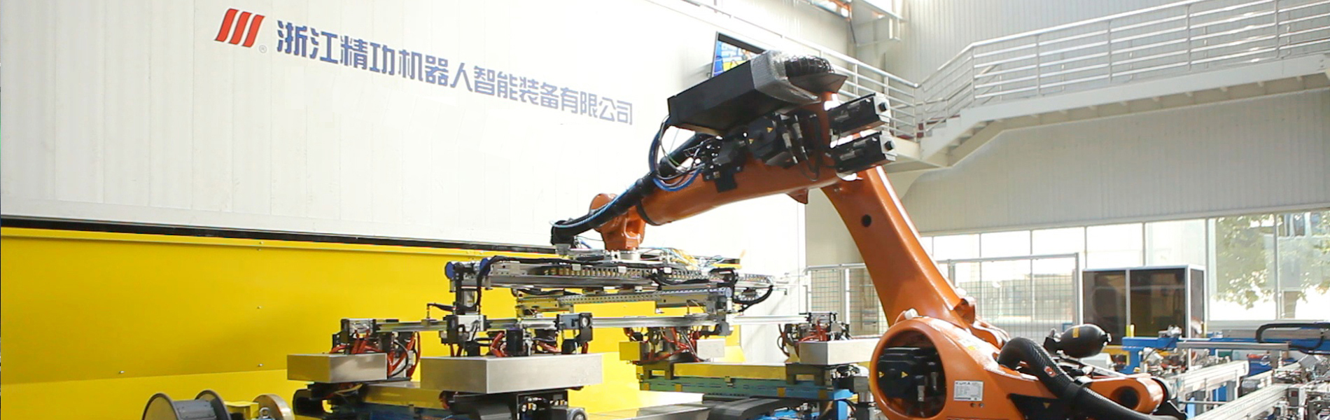


Cabinet frame welding line adopts robotics automatic operate.
Frame material: SPCC
Frame dimension: length 600-1200mm, width 600-1200mm, height 1500-2500mm. In order to allow automatic assembly, all sheet metal parts which has mating requirements will need to be produced as per accuracy requirement GB/T 13914-2002 FT3 tolerance level. See supplement drawings for specific requirements.
Cabinet frame welding line Must meet functional requirements
Delivering linear speed 0-20m/min adjustable.
One temporary storing area near the loading rack is required. Material rack needs to have wheels so that it can move from the temporary storage area to the work position.
Different specifications of products can be quickly switched through the main control touch screen.
The left and right frame assembly tooling needs to be produced in quick change type, which is convenient for manual quick change. The left and right frames are loaded manually, but they can be assembled automatically, and equipped with sensors to prevent mistakes or missing in loading.
When the left and right frame are being automatically assembled and when the frame bolts being welded, starting requires button pressing by 2 hands.
The left and right frame welding positions require automatic adjustment of the tooling when changing the specification. And the tooling must have a detecting device to detect whether the work piece is in place. Welding must begin after clamping tight to avoid welding gun from colliding.
The gripper adopts octagonal tube design.
The welding room is made of aluminum profile frame or steel structure welded frame, and the door is must have a safety lock.
When the overall frame is assembled, the left and right frames are automatically delivered to position by the wire body and the truss, and the four short beams are manually placed into the positioning tool, and the two-hand start button is required to start the automatic assembly.
The equipment is sealed with an aluminum profile grid fence, which requires the personnel to unlock the safety door lock before entering.
Cabinet frame welding line Frame welding process description and cycle time analysis
2.1 Process analysis and description
The entire frame production line consists 8 parts: OP10 left and right frame assembly unit and stud welding unit, OP20 left and right frame welding unit and robot loading and unloading, OP30 frame overall assembly unit and integral frame loading and unloading truss manipulator, OP40 overall frame welding unit and loading and unloading truss manipulator, OP50 blanking conveyor line and the first inspection position, dust removal system, electrical control system, and aluminum profile fence.
|
Part 1: The work position includes one set of stud welding machine, one stud welding machine workbench, one stud loading vibrating disc and placing table, one set of left and right frame automatic assembling tooling, one section of top plate conveying line, 4 loading racks, and one touch screen, etc.
process: Manually put the short beam into the stud welding tooling, the sensor detects if it’s in place, the two-hand start button flashes green, press the two-hand start button, the tooling locates and clamps the stud and the stud welding system conducts automatic welding. After welding finishes, the stud is taken out and put into the left and right frame assembly tooling. Put the rest of the beams and the iron tee into the assembly tooling at one time. The sensor detects part missing, misplacement, and proper positioning. When the green light of the two-hand start button flashes, press the two-hand start button to start the automatic assembly. After the assembly, the left and right frame tooling are automatically lowered, and the conveyor line moves the left and right frames to the OP20 loading position, and the positioning tools automatically jacks up to position.
|
The layout is shown as below:
|
|
Part 2: This work position includes one loading positioning tool, one left and right frame loading and unloading robot, one turntable positioner, two sets of left and right frame welding tools, two welding robots, two sets of welding systems, and one general control cabinet, display screen, one gripper, one welding room, one robot gantry mounting bracket, Description: 1. The gripper is made of octagonal tube, and the manual change pin position for fixing different size. 2. The left and right frame tooling is compatible for welding the upper and lower frames too, and can be adjusted steplessly. The adjustment range is 600-1200mm wide and 600-2500mm long.
Process : OP20 loading robot loads the workpiece and put it into welding tooling. The sensor detects the workpiece in position and automatically clamps & position the workpiece. The horizontal axis of the positioner rotates 180°, two welding robots start welding. When the welding finishes, the positioner horizontally reverse 180°. The loading and unloading robot flips the frame 180° and place it to the OP30 truss gripper (the following welded frame is placed directly on the OP30 jacking transitional tooling without flipping). Then load the the left and right frames assembled with the OP10 onto OP20 welding tooling, the above process repeats; |
as shown in Figure (1)
as shown in Figure 2
 |
|
Part 3: one truss gripper, one loading positioning tooling, one set of overall frame assembly & positioning tooling, one section of top plate conveying line.
Process: the truss gripper puts the first welded left and right frame into the OP30 line body jacking positioning transitional tools, which will then descends and place the welded frame onto the line body. Switch on the positioning device to automatically start the line body to send the left and right frames to the overall frame assembly positioning tooling, which will jack-up to position. Short cross beam will be manually placed to the integral frame positioning tooling. Meanwhile, the truss gripper descends to move the second welded workpiece from the overworked to the integral assembly. Position, then start the automatic assembly button, the overall frame fits, the overall frame positioning tooling is lowered, the frame is moved to the OP40 tooling loading positioning fixture position, the clamp is jacked up and positioned, waiting for the OP40 truss gripper to grab. |
 |
|
Part 4: Includes a 2-axis truss, four welding robots, four sets o welding systems, one positioner, two sets of welding tooling, one overall frame loading and unloading truss manipulator, one welding room. The OP40 truss gripper grabs the overall frame of the loading position and puts it into the OP40 welding tooling, the welding tooling is positioned and clamped in place, and the positioner rotated 180° horizontally. Four welding robots start welding. The OP40 truss gripper grabs another overall frame of the loading position and puts it into OP40 welding tooling. Then welding positioner rotates 180° horizontally in reverse direction. When the frame is less than 2300mm, the OP50 jacking rotary translation mechanism rotates 90° first. The truss gripper puts the welded overall frame on the OP50 jacking rotary translation mechanism (When the height is greater than or equal to 2300mm, the OP50 jacking rotation mechanism does not rotate. The welded overall frame will be put directly top of the OP50 jacking rotary translation mechanism) |
|
|
Part 5: Includes one jacking rotary translation mechanism, three sections of roller conveyor line, and one set of frame flipping mechanism. Process 1: The jacking rotary translation mechanism starts to translate the work piece to the roller conveyor. The roller conveyor moves the work piece to flipping mechanism position and the flipping mechanism fixes the workpiece and flips it by 90° , and wait for the spraying tooling to come in place.Process 2: Start the first inspection mode, manually inspects the first inspection welding results. If the results pass, then the auto mode is activated (if not, manual repair weld it, and check the equipment, find out the reasons why the results fail and fix the problems). The jacking rotary translation mechanism automatically starts to translate the workpiece to the roller conveyor. The roller conveyor moves the frame to the slipping mechanism position, and the flipping mechanism fixes and flips the workpiece by 90°, and wait for the spraying tooling to come in place. |
 |
2.2 Cabinet frame welding line cycle time analysis
The cycle time analysis is calculated according to the specific specifications of the product leveling time. Different specifications will have different cycle time calculations.
Cycle time requirement: 2min/piece
|
General layout |
 |
|
equipment plane layout |
 |
|
Equipment 3d schematic |
 |
4、work station main configuration list
|
|
Name |
Description |
|
Units |
|
|
1 |
Left right frame assembly unit |
Frame assembly conveyor line |
MODULAR/OTHER |
SET |
1 |
|
Assembly tooling |
JINGGONG ROBOTICS |
SET |
1 |
||
|
Frame bolts auto welding system |
HBS |
SET |
1 |
||
|
Bolts welding tooling |
JINGGONG ROBOTICS |
SET |
1 |
||
|
Safety fence |
LOCAL |
SET |
1 |
||
|
Loading frame |
JINGGONG ROBOTICS |
SET |
4 |
||
|
2 |
Left right frame welding unit |
Left right frame loading positioning tooling |
JINGGONG ROBOTICS |
SET |
1 |
|
transportation robot KR150 R2700 extra
|
KUKA |
SET |
1 |
||
|
Transportation robot base |
JINGGONG ROBOTICS |
SET |
1 |
||
|
Transportation gripper |
JINGGONG ROBOTICS |
SET |
1 |
||
|
Welding robot KR 16 L8 arc HW (reverse mounting) |
KUKA |
SET |
2 |
||
|
Welding robot mounting gantry |
JINGGONG ROBOTICS |
SET |
1 |
||
|
2 -work position - turntable AT1000 |
FIBRO |
SET |
1 |
||
|
2 -work position - turntable servo |
SEW |
SET |
1 |
||
|
2 -work position - turntable base |
FIBRO |
SET |
1 |
||
|
H type slewing frame |
JINGGONG ROBOTICS |
SET |
1 |
||
|
Single axis positioner base board |
JINGGONG ROBOTICS |
SET |
2 |
||
|
Single axis positioner (including reducer) |
JINGGONG ROBOTICS+SUMITOMO |
SET |
2 |
||
|
Sing axis positioner servo motor (including drive) |
SIEMENS/OTHER |
SET |
2 |
||
|
Welding fixture |
JINGGONG ROBOTICS |
SET |
2 |
||
|
X axis double slider lock long electric cylinder |
THOMSON/OTHER |
SET |
2 |
||
|
X axis double slider long electric cylinder servo motor (including drive) |
SIEMENS/OTHER |
SET |
2 |
||
|
Y axis double slider electric cylinder |
THOMSON/OTHER |
SET |
4 |
||
|
Y axis double slider electric cylinder servo motor (including drive) |
SIEMENS/OTHER |
SET |
4 |
||
|
XY axis double slider electric cylinder reducer |
APEX/OTHER |
SET |
6 |
||
|
Welding protection room |
JINGGONG ROBOTICS |
SET |
1 |
||
|
CMT3200 welding system |
FRONIUS |
SET |
2 |
||
|
Gun cleaner |
TBI/OTHER |
SET |
2 |
||
|
Safety fence |
LOCAL |
SET |
1 |
||
|
3 |
Frame overall assembly unit |
assembled top plate conveyor |
MODULAR/OTHER |
SET |
1 |
|
Loading positioning auxiliary tooling |
JINGGONG ROBOTICS |
SET |
1 |
||
|
Gripper |
JINGGONG ROBOTICS |
SET |
1 |
||
|
overall frame positioning mechanism |
JINGGONG ROBOTICS |
SET |
1 |
||
|
truss |
JINGGONG ROBOTICS |
SET |
1 |
||
|
Truss X axis servo motor (including drive) |
SIEMENS/OTHER |
SET |
1 |
||
|
Truss Yaxis servo motor (including drive) |
SIEMENS/OTHER |
SET |
1 |
||
|
Loading frame |
JINGGONG ROBOTICS |
SET |
2 |
||
|
4 |
Whole unit welding |
Truss |
LOCAL |
SET |
1 |
|
Loading conveyor |
MODULAR/OTHER |
SET |
1 |
||
|
Overall frame loading positioning tooling |
JINGGONG ROBOTICS |
SET |
1 |
||
|
X axis servo motor (including drive) |
SIEMENS/OTHER |
SET |
1 |
||
|
Z axis servo motor (including drive) |
SIEMENS/OTHER |
SET |
1 |
||
|
Tooling |
JINGGONG ROBOTICS+OTHER |
SET |
1 |
||
|
2-work position-turntable AT1250 |
FIBRO |
SET |
1 |
||
|
2-work position-turntable AT1250 servo drive |
SEW |
SET |
1 |
||
|
2-work position-turntable base |
FIBRO |
SET |
1 |
||
|
H type slewing base frame |
JINGGONG ROBOTICS |
SET |
1 |
||
|
L=0.6m Single axis positioner translation servo electric servo cylinder stroke L=0.6m |
LIMTEC/OTHER |
SET |
2 |
||
|
Single axis positioner translation guide rail L=1m (including sliding block) |
THK/HIWIN |
SET |
4 |
||
|
Single axis positioner mounting rack |
JINGGONG ROBOTICS |
SET |
2 |
||
|
Single axis positioner (including reducer) |
JINGGONG ROBOTICS+OTHER |
SET |
4 |
||
|
Single axis positioner servo motor (including drive) |
SIEMENS/OTHER |
SET |
4 |
||
|
Single axis positioner Y axis motion double slider electric cylinder |
THOMSON/OTHER |
SET |
4 |
||
|
Single axis positioner Y axis motion double slider electric cylinder servo motor (including drive) |
SIEMENS/OTHER |
SET |
4 |
||
|
Single axis positioner Y axis motion double slider electric cylinder reducer |
APEX/OTHER |
SET |
4 |
||
|
Single axis positioner Z axis motion double slider electric cylinder |
THOMSON/OTHER |
SET |
8 |
||
|
Single axis positioner Z axis motion double slider electric cylinder servo motor (including drive) |
SIEMENS/OTHER |
SET |
8 |
||
|
Single axis positioner Z axis motion double slider eietric cylinder reducer |
APEX/OTHER |
SET |
8 |
||
|
Single axis positioner Y axis motion slider L=1500mm(including slider) |
THK/HIWIN |
SET |
8 |
||
|
Single axis positioner Z axis motion slider L=1500 mm(including slider) |
THK/HIWIN |
SET |
8 |
||
|
Guide rail locking mechanism |
LOCAL |
SET |
16 |
||
|
Welding fixture |
JINGGONG ROBOTICS |
SET |
2 |
||
|
Welding robot KR 16 L8 arc HW |
KUKA |
SET |
2 |
||
|
Welding robot base |
JINGGONG ROBOTICS |
SET |
2 |
||
|
Welding robot reverse mounting gantry column |
JINGGONG ROBOTICS |
SET |
2 |
||
|
Welding robot reverse mounting gantry cross beam. L=7m |
JINGGONG ROBOTICS |
SET |
1 |
||
|
Welding robot translation guide rail. L=1m (including glider) |
JINGGONG ROBOTICS |
SET |
4 |
||
|
Welding robot translation rod-less gas cylinder |
FESTO |
SET |
2 |
||
|
Welding robot KR 5 arc HW (reverse mounting) |
KUKA |
SET |
2 |
||
|
Welding robot base |
KUKA |
SET |
2 |
||
|
Welding protection room |
JINGGONG ROBOTICS |
SET |
1 |
||
|
CMT3200 welding system |
FRONIUS |
SET |
4 |
||
|
Gun cleaner |
TBI/OTHER |
SET |
4 |
||
|
Safety fence |
LOCAL |
SET |
1 |
||
|
5 |
Inspection unit |
Jacking rotary translation inspection line |
MODULAR/OTHER |
SET |
1 |
|
Discharging roller line (short) |
MODULAR/OTHER |
SET |
1 |
||
|
Discharging roller line long) |
MODULAR/OTHER |
SET |
2 |
||
|
Jacking transverse mechanism |
MODULAR/OTHER |
SET |
2 |
||
|
Flipping mechanism (including roller line) |
MODULAR/OTHER |
SET |
1 |
||
|
Frame positioning mechanism |
JINGGONG ROBOTICS |
SET |
2 |
||
|
Double slider electric cylinder |
THOMSON/OTHER |
SET |
4 |
||
|
Double slider electric cylinder servo motor (including drive) |
SIEMENS/OTHER |
SET |
4 |
||
|
Double slider electric cylinder reducer |
APEX/OTHER |
SET |
4 |
||
|
Manual welding system |
LINCOLN |
SET |
1 |
||
|
Safety fence |
LOCAL |
SET |
1 |
||
|
6 |
Dust removal system
|
DFO 3-18 |
Donaldson/OTHER |
SET |
1 |
|
7 |
Electric control system |
|
SIEMENS/OTHER |
SET |
1 |
Dust removal system
Big welding room equipped with DFO 3-18.
Dust, soot and oil mist, dust collector, filter & spare parts.
dust collector
welding system——TPS 3200 CMT
Cold Metal Transition (CMT), a milestone in the history of welding. The welding program of the TPS 3200 CMT achieved by a fully digital microprocessor controlled inverter that is not only being used for MIG/MAG welding, but also for TIG and manual welding. The innovation of CMT technology is that it also incorporates the wire feeding system into the control of the entire program, which can effectively control the heat input without any splash on the workpiece.
The TPS 3200CMT technology with a maximum current of 400A has been successfully applied in the automotive industry, aerospace and construction, steel structures, etc. CMT technology has a widely application range and is suitable for any thin plate or even 0.3mm ultra-thin plate. It can realize MIG brazing of galvanized sheet and connection of carbon steel and aluminum.
Electric control system
The control system uses SIEMENS PLC to collect signals such as collected by sensors into the CPU through the network, and deliver the processed signals to the execution components through the network.
Configured electric control cabinet and operation box.
Pneumatic components adopt FESTO or SMC products
The system is equipped with mechanical start button switch. The operation has manual / automatic mode.
Relative parameter can be set in via HMI.
Safety fence is equipped to guarantee personnel safety.
Floor: Regular cement floor. After the whole station is leveled, it can be fixed to the ground by chemical bolts or expansion bolts; the bearing capacity of the ground is required to be <25KN/ m2
Temperature: 5~45℃
Humidity: 2075%RH
Vibration: less than 0.5G
Power requirements: 380V ± 10%; 3-phase five-wire system; 50HZ ± 2%
ZHEJIANG JINGGONG ROBOTICS & INTELLIGENT EQUIPMENT CO.,LTD is a high-tech enterprise, with robot technology as the core, to provide digital intelligent integration solutions.Parent company ZHEJIANG JINGGONG SCIENCE & TECHNOLOGY CO., LTD. registered capital of 450 million, it went public at Shenzhen Stock Exchange in 2004, the stock code is 002006.
 English
 Deutsch
 Español
 Русский
 Français
 عربية لغة
 中文
中文


